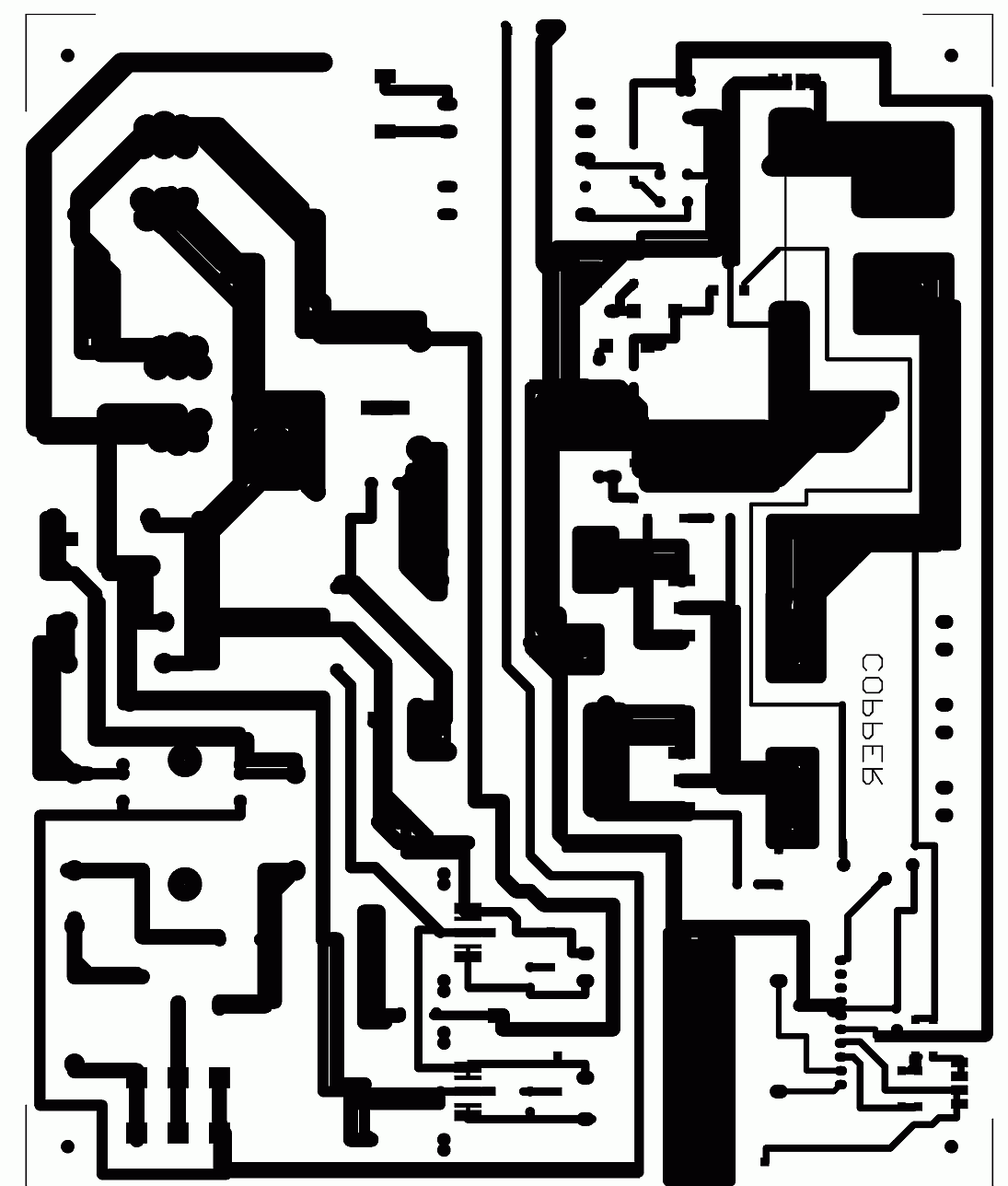

smps switching power supply transformer april 29th, 2018 - a new cad tool on the internet for switching power supplies poweresim. | MAY 1ST, 2018 - HIGH FREQUENCY TRANSFORMER DESIGN THE FIRST STEP TO CALCULATE A HIGH FREQUENCY TRANSFORMER IS USUALLY TO CHOOSE AN APPROPRIATE CORE WITH THE HELP OF THE DATA''poweresim free 3 / 7. Starichok51 share of 18 program until it was presented as a very popular used. Programs prepared by Russian-born Vladimir Denisenko sharing a person known as a Russian electronic forum Starichok51. (kHz) FSCM0565RC STB, LCD Monitor 70 85 2.5 650 2.2 66 Yes TO220-5L FSCM0565RD STB, LCD Monitor 50 65 2.5 650 2.2 66 Yes D2PAK-5L FSCM0765RC STB, LCD Monitor 85 95 3 650 1.6 66 Yes TO220-5L FSCM0765RD STB, LCD Monitor 60 70 3 650 1.6 66 Yes D2PAK-5L | Before "Advanced SMPS Transformer design program" ExcellentIT and "Ir2153 SG3525 Frequency Calculation Programs for Switch mode power supplies with raisers" shared a very useful programs. | Switching Frequency Package Number 85-265VAC 230VAC ☑5% Limit (A) (V) Frequency (V) Mod. You can therefore connect an RC filter to the output to eliminate harmonics and obtain an almost perfect sine wave. The high power output certainly contains many harmonics of 3, 5, 7, etc, being the square wave. Hello A simple solution is to generate a square wave frequency with a power SiC MOSFET.A good estimation for the inductor ripple current is 20% to 40% of the output current, or 0.2 < Kind < 0.4. Kind = estimated coefficient that represents the amount of inductor ripple current relative to the maximum output current. Fsw = switching frequency of the converter.


 0 kommentar(er)
